Page 3 - FRE Composites | Specifications | Split Conduit
P. 3
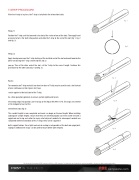
T-STRIP PROCEDUREAfter the H-strip is in place, the T-strip is installed in the intermittent slots.Step 1:Position the T-strip such that one end is located at the center of one of the slots. Then apply hand pressure to force the teeth into position and slide the T-strip to the end of the slot ( g. 1, g. 2 and g. 3).Step 2:Apply hand pressure on the T-strip starting at the installed end of the slot and work towards the other end forcing the T-strip’s teeth into the slot asyou go. Then at the other end of the slot, cut the T-strip to the correct length. Continue this procedure for the other slots ( g. 4 and g. 5).Note:To economize on T-strip material, two short sections of T-strip may be used to seal a slot instead of one continuous section. Again, duct tapecan be applied at the butt-joint of the T-strip.As a nal operation (optional), to ensure system rigidity and to lockthe sealing strips into position, use tie wraps or the Repair Kit (#40-0174). Tie wraps are inserted at the midpoint of each of theintermittent slots ( g. 6)This conduit length is now completed and work can begin on the next length. When installing subsequent conduit lengths, ensure that they are oriented properly such that a bell end and a spigot end are facing each other for every set of adjacent conduits. As subsequent conduits are completed with the installation of H & T-strips, they can be coupled inbell & spigot fashion. Since tight mechanical sealing is not possible at the bell and spigot joint, taping or additional tie wraps can be used to ensure better joint integrity. This document is the property of FRE Composites (2005) Inc. (“FRE Composites”). It shall not be used, reproduced, copied or transmitted to other persons without written authorization. composite.com